Perforated Tiles vs Directional Flow Grilles: Where to Put Each One on Your Raised Floor (and Why It Matters More Than You Think)

Whether you distribute perforated tile or directional flow grille across your raised floor is what determines whether your data center has hot spots or uniform flow. Choosing the wrong type and the wrong distribution pattern generates energy inefficiency, equipment degradation, and eventually premature hardware failure. This article covers when to use each type, how to calculate how many you need, and the typical installation mistakes that cost money.
What follows applies to data centers with a raised floor and cold aisle containment. For DCs with overhead ducts or without containment, the airflow dynamics are different and this article applies only in part.
Why the tile type choice matters
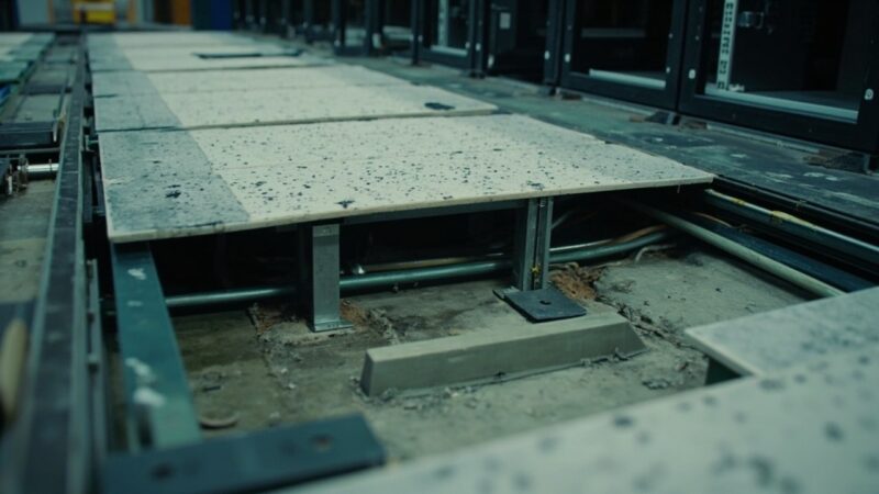
The function of the perforated tile and the directional flow grille is the same: let cold air from the plenum rise into the cold aisle. But they do it with different characteristics:
- Standard perforated tile: plate with 25% to 56% open area, with uniform perforations (typically 8mm). Distributes air evenly in all directions. Required static pressure: 0.05 to 0.15 inWC.
- Directional flow grille (FFG, Flow-Through Grille): grille with an adjustable damper that directs air in a specific direction (typically 4-way or radial). Open area 50-65%. Required static pressure: 0.10 to 0.30 inWC.
- Solid tile: no perforation. Used in zones where air must NOT pass through (hot aisle, preparation areas).
The choice between perforated tile and directional flow grille depends on the rack geometry, the CRAC/CRAH unit feeding the air, and the hot spots you are trying to fix. There is no single rule for the whole DC.
When to use standard perforated tile
Perforated tile is the right choice for:
- Even air distribution in racks with uniform thermal load (typically 5-10 kW per rack). If all your racks have similar draw, standard perforated tile works well.
- Rack fronts with air intake grilles at the bottom (typical of 1U-2U servers). The air coming out through the perforated tile goes directly into the servers.
- Regular rack layout, with no significant variation rack to rack. Rectangular room with aligned racks and a 1.2 m cold aisle.
For a DC with 30 racks averaging 7 kW, a rectangular layout, and cold aisle containment with panels, 25% open-area perforated tile (the most common, G4-rated for G4 filters) covers 80% of the cold aisle area in front of the racks. The remaining 20% are solid tiles for zones without racks.
When to use a directional flow grille
The directional flow grille (FFG) is the right choice for:
- Fixing specific hot spots. If instrumentation shows a zone with an air intake temperature 5°C above the rest of the room, an FFG aimed at the problem rack is the most surgical solution.
- High density per rack (>15 kW per rack). High-density servers (4U with 2 CPUs, GPUs, all-flash storage) consume more airflow. The FFG directs the air exactly where it is needed without wasting it.
- Long distances between the CRAC and the rack (>15 meters). If the air has to travel a long way through the plenum before rising, it loses static pressure. The FFG compensates for that loss because it has a larger open area than standard perforated tile.
- Irregular rack layout. If you have racks in different orientations or configurations, FFGs let you direct the air individually for each rack.
The additional cost of FFGs versus standard perforated tiles is 3-5x. That is why they are used where the return is clear: high density, identified hot spots, or critical racks. For standard-density zones, perforated tile is enough and cheaper.
How to calculate how many you need
The calculation depends on three variables: thermal load per rack, distance to the CRAC, and static pressure available in the plenum. Simplified sizing formula:
- Required airflow per rack = thermal load (kW) × 3,517 / (1.08 × delta T). For a 10 kW rack with a 13°C delta T (typical), that is 10 × 3,517 / (1.08 × 13) = 2,506 CFM per rack.
- Airflow per 25% perforated tile (typical, 600×600 mm): around 350-450 CFM at 0.10 inWC of pressure. To reach 2,506 CFM you need between 6 and 8 perforated tiles in front of the rack.
- Airflow per FFG (600×600 mm with the damper open): 600-800 CFM at 0.15 inWC. For the same rack, 3-4 FFGs are enough. That is why FFGs are useful at high density.
- Static pressure in the plenum: your CRAC/CRAH must deliver 0.10-0.15 inWC in the plenum for air to rise through the perforated tiles, or 0.15-0.20 inWC if you use FFGs. If pressure drops below 0.05 inWC in distant zones, you will get hot spots.
For a 200 m² DC with 50 racks averaging 10 kW: 50 × 7 ≈ 350 perforated tiles (the area in front of the racks). The factor 7 is the midpoint of the 6 to 8 tiles per rack range calculated in the previous paragraph (average between minimum and maximum according to the CFM required per rack). With solid tiles everywhere else (hot aisles, preparation zones), the total tile count is between 500 and 600.
Typical distribution mistakes
The 5 most common mistakes that cause hot spots:
- Perforated tiles misaligned with the racks. If you put the perforation grille on a tile that sits between racks, the air rises into the aisle, not into the server. The perforation must be exactly in front of the rack, not between racks.
- Perforated tiles in the hot aisle. This recirculates hot air through the plenum and raises the intake temperature on all racks. The hot aisle zone must have solid tiles.
- Perforated tiles distributed evenly without considering distance to the CRAC. The racks farthest from the CRAC need more perforation or FFGs to compensate for the static pressure loss.
- Too many perforated tiles, creating an air short circuit. If you have 50%+ of the area perforated, air exits too fast through the first zones and never reaches the far zones. The correct distribution is 30-40% of the raised floor area perforated.
- Swapping perforated tiles for solid ones to fix hot spots without measuring pressure. If you remove perforated tiles to ‘force’ air to another zone, all you do is raise the total static pressure, which increases the CRAC fan power draw. The hot spot can move without being solved.
Before moving tiles, instrument. Temperature and pressure sensors on the cold aisle of each rack. An airflow meter at the CRAC outlet. Without data, you are guessing.
How to adjust the distribution when there is a hot spot
The correct procedure when a specific rack has an intake temperature 5°C above target (typically 22-24°C):
- Verify the rack has the correct airflow (CFM). A dirty server intake filter can reduce airflow by 30-50% without raising room temperature. Check the server filters first.
- If the filter is clean, measure static pressure in the plenum in front of the rack. If it is below 0.05 inWC, the problem is pressure loss from distance or from cable blocking in the plenum.
- If the pressure is adequate, the problem is tile distribution. Replace 1-2 perforated tiles in front of the rack with FFGs with the damper opened all the way. This increases local airflow without affecting the rest.
- Measure again after the change. If the intake temperature drops 3-5°C, the adjustment worked. If it does not drop, the problem is something else (excessive thermal load, undersized CRAC, air bypass).
Fine-tuning tiles is continuous work, not a one-time event. As your DC evolves (more equipment, redistributed loads), the tile distribution also needs to be revisited. Typically every 6-12 months.
Costs in Mexico for 2025-2026
To put concrete numbers on it:
- Standard 600×600 mm perforated tile with 25% open area: $1,800-2,800 MXN per installed unit.
- Perforated tile with 56% open area (high density): $3,500-5,500 MXN per installed unit.
- Directional flow grille (FFG) with manual damper: $8,000-14,000 MXN per installed unit.
- Directional flow grille with motorized damper (BMS control): $18,000-32,000 MXN per installed unit. Motorized control lets you adjust airflow remotely based on intake temperature.
- Solid tile: $1,400-2,200 MXN per installed unit.
For a 200 m² DC with 50 racks at 10 kW, typical distribution: 60% solid, 30% standard perforated, 10% FFG. Total cost of the tile system: between $1.0M and $1.8M MXN. It is one of the components where a site provider can most easily quote you wrong. Ask for a breakdown by type and quantity.
The correct distribution of perforated tiles and FFGs is what separates an efficient data center (PUE 1.3) from an inefficient one (PUE 1.6+). The difference is between $200,000 MXN per year and $1.2M MXN per year in energy for a 500 kW DC. A well-designed tile system pays for itself.
Sources
- TIA-942-B-2023 — Telecommunications Infrastructure Standard for Data Centers — https://www.tia.org/standards/tia-942
- BICSI 002-2024 — Data Center Design: Raised Floor and Airflow Management — https://www.bicsi.org/standards/data-center
- Uptime Institute — Tier Topology: Airflow Management and Containment Strategies — https://datacenter.uptimeinstitute.com/
- Schneider Electric — Data Center Physical Infrastructure: Air Distribution and Perforated Tile Design — https://www.se.com/mx/es/product-category/data-centers/
Want to master this?
Noxtel Academy →