Electrical service entrance vs data cabling in data center: why mixing them in the same tray can cost 3x more
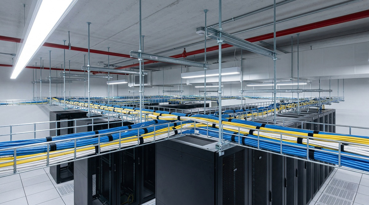
When you design the cable path in a data center, mixing the electrical service entrance (power cables that feed equipment) with data cabling (network cables, fiber, copper) in the same tray is one of the errors that costs the most in downtime. The electromagnetic interference that the service entrance generates on the data cables, combined with the lack of physical separation required by the electrical code, generates everything from intermittent network errors to physical equipment damage from induced voltage spikes. This article covers why separation is critical, what exactly the regulations say, and the 3 typical errors that cost 8+ hours of downtime when mixed.
What follows applies to data centers with three-phase electrical service entrance (typical in Mexico: 220V or 480V) and structured data cabling (Cat6, Cat6A, fiber optic). The principle also applies to low voltages (110V) but with lower impact.
Why physical separation is necessary (not just regulatory)
The fundamental problem is electromagnetic interference (EMI):
- The three-phase electrical service entrance generates alternating electromagnetic fields at 60 Hz (the grid frequency in Mexico). These fields couple inductively to any nearby parallel conductor.
- Copper data cabling (Cat6, Cat6A) transmits low-amplitude differential signals (typically 1-3 V). The magnetic fields from the service entrance can induce voltage in these cables, corrupting the signal.
- Fiber optic is immune to EMI (it transmits light, not electricity). But if you have data copper cables in the same tray, they are still affected even though the fiber is not.
The operational result: intermittent network errors (lost packets, retransmissions, high latency), and in extreme cases, induced voltage spikes that physically damage the network ports of equipment. The damage appears weeks or months after initial deployment, when nobody connects the symptoms to the nearby service entrance.
What the Mexican electrical code says (NOM-001-SEDE)
The Norma Oficial Mexicana NOM-001-SEDE-2012 (electrical installations) is clear:
- Power cables and data cables must be in separate raceways. The minimum physical separation is a function of voltage and current of the power cables.
- For 220V or 480V three-phase service entrance, the minimum separation between power cables and data cables is 30 cm. This applies to any copper data conductor.
- If physical separation is not possible due to architectural constraints, continuous metallic barrier between the two systems is required (typically steel tray with cover).
- Fiber optic can share a tray with the electrical service entrance (it is immune to EMI), but the code recommends separation for consistency.
The code is local law. If your DC has mixed cables and an incident occurs (person receives shock, equipment is damaged), the post-incident inspection will detect the mix and insurance may deny coverage for non-compliance.
The 3 correct ways to separate the cables
Operational solutions:
The typical error is using trays with ‘plastic dividers’ or without a continuous divider. This does NOT comply with NOM-001-SEDE because the divider is not continuous metal and does not provide effective electromagnetic isolation. Electrical inspection detects it in any audit.
When fiber optic can share with the service entrance
Fiber optic has unique electrical properties:
- It does not conduct electricity, only light. It is completely immune to EMI.
- It does not generate EMI (it has no radiated electrical signals).
- It can share a tray with the electrical service entrance without technical issue. The code allows it.
But fiber optic in the same tray as the service entrance has a practical issue: if the service entrance heats up (typical in normal operation), the fiber can be affected by heat. The typical fiber optic specification is 0-70 degrees C operation. An overloaded service entrance can reach 60-80 degrees C in the tray. Recommendation: maintain 15 cm separation even for fiber, to avoid thermal issues.
The real case: 8 hours of downtime from a shared tray
Real operation at an enterprise client in 2023. DC with 30 racks, a single shared tray between service entrance and Cat6A data cabling. After 18 months of operation, intermittent errors started on the network: lost packets, random server disconnections, variable latency.
- Initial diagnosis: they thought it was a switch problem. 2 switches were replaced without resolving it.
- After: they thought it was a cable problem. 20 patch cords were re-cabled without resolving it.
- After 6 months of diagnosis, the electrical provider detected that the 480V three-phase service entrance was inducing enough EMI to corrupt the Cat6A signals.
Solution applied: install a separate tray for service entrance, move data cables to independent tray. Work time: 12 hours (including rack relocation to access the tray). Associated downtime: 8 hours during migration. Total cost: USD $14,500 (approx. $250,000 MXN) in labor + 8 hours of downtime that affected operations.
Operational lessons: (1) correct physical separation from the design costs 15% more in upfront CAPEX, saves USD $14,500 (approx. $250,000 MXN) in the first incident; (2) induced EMI is invisible until it is massive; (3) the problem appears months after deployment, complicating diagnosis.
How to audit your current DC
Steps to verify if your DC complies with separation:
- Visual inspection of trays. Is the electrical service entrance and the data cabling in physically separate trays? Or do they share the same tray without a continuous divider?
- EMI measurement on data cables. With an electromagnetic field meter, verify that the field in the data tray is less than 1 V/m. If it is higher, there is significant EMI.
- Network error test. Run an extended ping between two servers connected by cables in the same tray as the service entrance. If there is packet loss >0.1%, there is interference.
- Verification with your electrical provider. Does the installation have a current NOM-001-SEDE certificate? Did the post-installation inspection verify separation?
If any of the 4 verifications fail, there is a design problem. The fix is typically to install a separate tray, with downtime of 4-12 hours depending on scope.
When structured cabling becomes critical
There are 3 scenarios where separation is NOT negotiable:
- Cat6A or higher data cables. 10 Gbps signaling is more sensitive to EMI than Cat5/100Mbps. If you use 10G over copper, separation is mandatory.
- Financial or trading applications. Sub-millisecond latency is affected by any interference. The difference between 0.5ms and 0.6ms can mean money lost in algorithmic trading.
- Medical or precision equipment. If your servers store medical data (HIPAA compliance) or scientific instrumentation data, separation is a regulatory requirement.
If your DC is in any of these 3 scenarios, assume mandatory separation from the design. Do not wait to have problems.
The additional CAPEX of doing separation correctly from the start
The cost overcharge of correct vs incorrect design:
The additional CAPEX is 1-3% of the total DC cost. Compared to USD $14,500 (approx. $250,000 MXN) for the first incident and possible data loss, the decision is obvious. The CFO who approves a simple tray to save is making a wrong total cost of ownership decision.
How to present the correct design to your provider
The electrical or site provider typically offers a simple tray by default. Your argument:
- ‘NOM-001-SEDE requires minimum physical separation of 30 cm between service entrance and data cabling. The simple tray does not comply. If an incident occurs, your certification is invalidated.’
- ‘The overcost of a double tray is 1-3% of the total. If we do not do it, we will have to do it in 2 years when the problem appears, with a cost 5-10x higher.’
- ‘The post-installation NOM-001-SEDE certificate verifies separation. If it fails, the electrical provider must correct it at their cost.’
- ‘As a client, I do not accept an installation that does not comply with code. If the provider insists on a simple tray, I look for another provider.’
A serious provider accepts the double tray without issue. One who insists on a simple tray is either because their margin is higher (cheaper for them) or because they do not know the code. Either of these two cases is a reason to look for an alternative.
When perpendicular crossing IS allowed
There is a special case:
- When the electrical service entrance crosses perpendicular to the data cabling (not parallel), EMI induction is minimal because the coupling surface is minimal.
- Perpendicular crossing is allowed by the code and does not require special separation, as long as it is at a 90-degree angle.
- Useful in sites where the two trays must cross due to architectural constraints.
This is NOT a license to mix cables. It is only for specific crossings where architecturally unavoidable. If your DC has more than 2-3 perpendicular crossings, the design is probably wrong from the start.
Summary: the 3 operational rules
To operate without surprises:
- Rule #1: Physically separate tray for service entrance and data cabling. If this is not possible due to space, a continuous metallic divider connected to ground.
- Rule #2: Post-installation verification with EMI meter. If the field is greater than 1 V/m in the data tray, there is a problem.
- Rule #3: Annual visual inspection of the separation. If cables were added later without respecting separation, correct immediately.
The 3 rules together comply with NOM-001-SEDE, avoid induced EMI, and prevent downtime from mysterious network errors. The additional CAPEX is marginal compared to the cost of the incident.
Sources
- NOM-001-SEDE-2012 — Electrical Installations (utilization) — https://www.gob.mx/profeco/documentos/nom-001-sede-2012
- TIA-942-B-2023 — Section 5: Cabling Infrastructure and Pathways — https://www.tia.org/standards/tia-942
- ANSI/TIA-568.2-D — Balanced Twisted-Pair Telecommunications Cabling — https://www.tia.org/standards
- NFPA 70 (NEC) 2023 — Article 725, 800, 820: Cable Separation Requirements — https://www.nfpa.org/codes-and-standards/all-codes-and-standards/list-of-codes-and-standards/detail?code=70
- IEEE Std 1100-2020 — Powering and Grounding Electronic Equipment (EMI Mitigation) — https://standards.ieee.org/standard/1100-2020.html
Want to master this?
Noxtel Academy →